Irregular Gears
This article is kind of long! I split it into three pages.
Gears are a fun subject. In 2010 MAKE: linked to a great video titled How to Make Organically Shaped Gears. The concept is straightforward:
- Take two existing gears of the desired gear ratio.
- Place the irregular gear on top of the smaller regular gear, and a piece of paper on the larger regular gear.
- Turn the regular gears and mark where the paper is obscured by the irregular gear. These are the sections that must be cut away for the two irregular gears to mesh properly.
- Cut away marked sections.
- Gaze in wonder at what you have wrought.
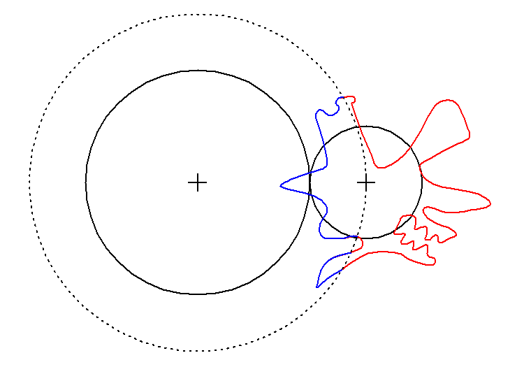
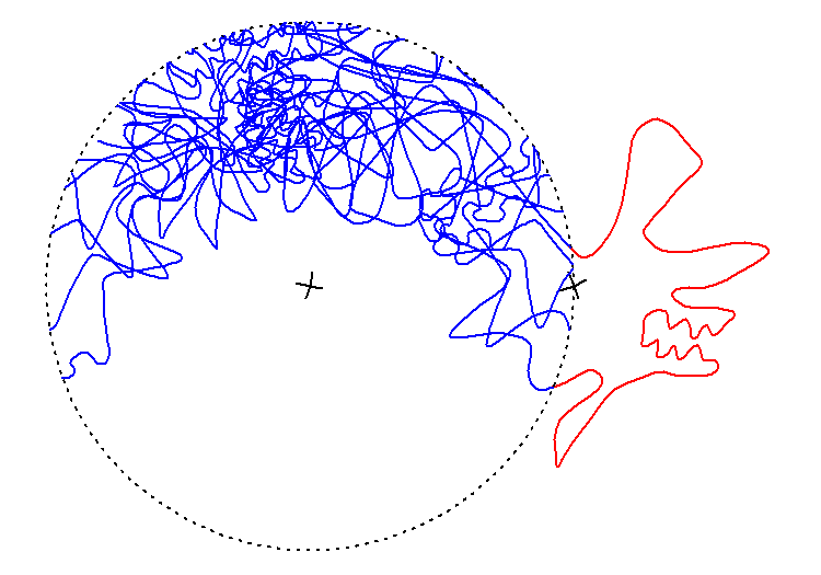
So, what's an equivalent process that can be implemented in a computer? Start with the essentials: two circles to become two gears.
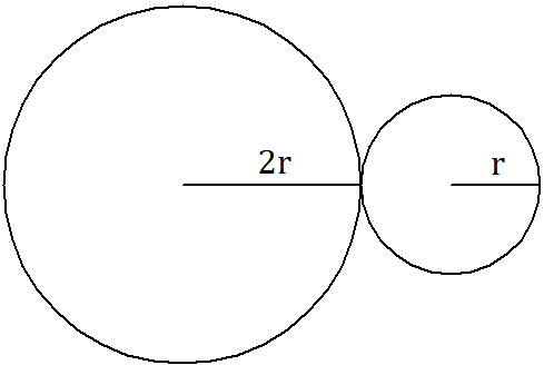
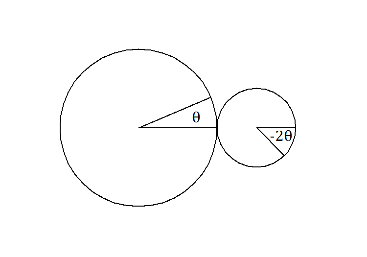
The output gear circle should have a radius that is some integer multiple of the input radius. In this case, it's twice the radius, but it could just as easily be one, or three, or ten times the radius. This is how we compute the gear ratio of our system. In this case, we've got a gear ratio of 2. You know, because the left gear is twice as big. This also means that if we turn the left gear by an angle θ, the right gear will turn by an angle -2θ, that is, in the opposite direction.
Cool. Now, the circle on the right will soon meet our input gear, and then we'll do some calculating and get the profile of the output gear on the left circle. The dashed line around the left circle represents the theoretical maximum radius our output gear could possibly have at any point. Chances are good it won't be anywhere near that big; it just makes a good cut-off point for calculations.
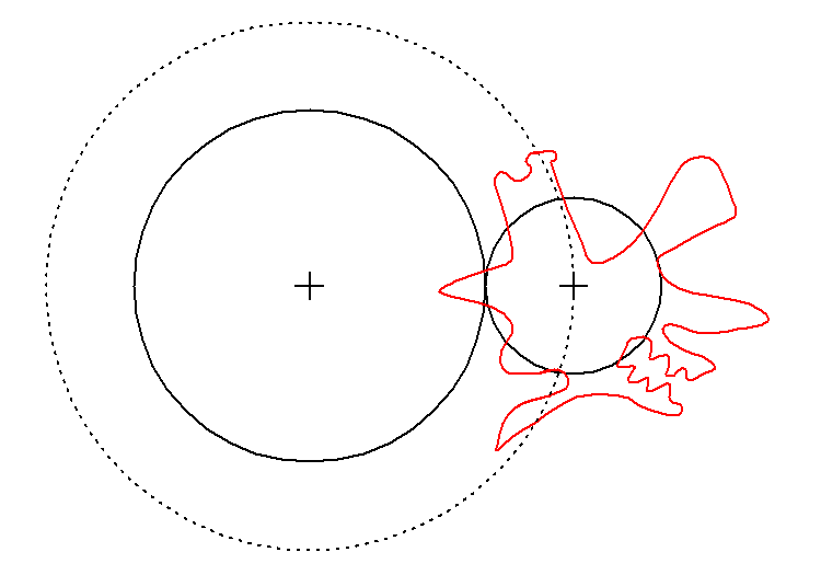
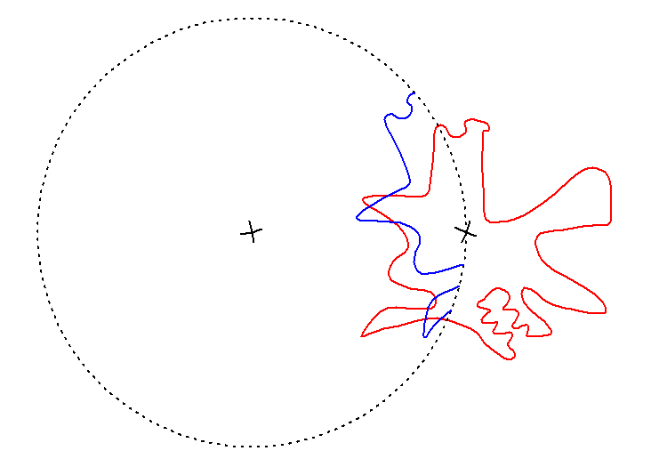
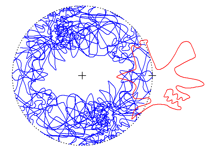
Right, the next step is to mark every point where the input gear falls within the dashed circle, then add those points to the output gear.
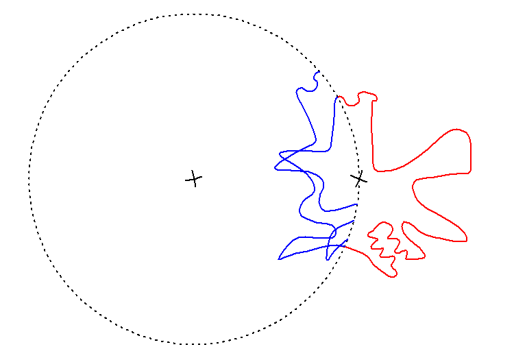
Next, we rotate the gears. The left one turns by some small step θ and the right one turns by -2θ...
...and then we mark which points are inside the dashed circle. Again.
Repeat a bunch of times. Here are eight steps:
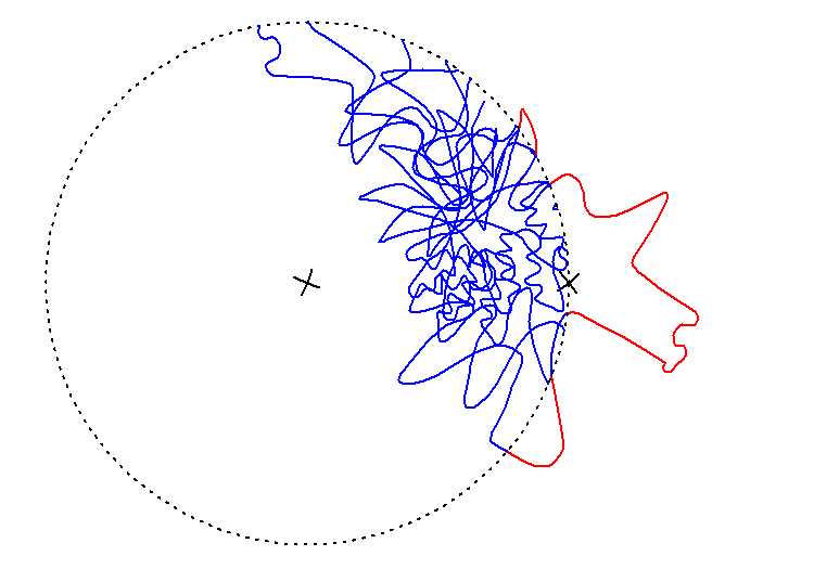
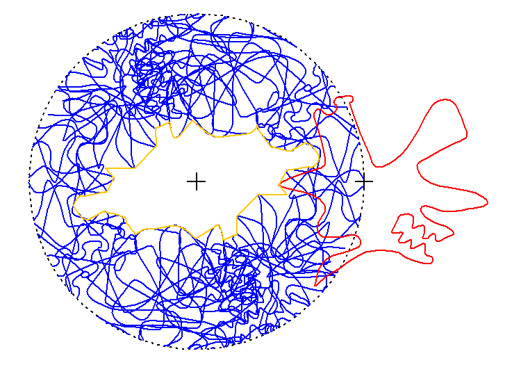
For this visual aid, I'm rotating the left and right gears by 10° and -20° each step. This is way too big to get good results, but this is just a demo. Come on. I'm not going to do 0.1° steps for the demo.
By the time we've turned the output gear halfway around, the input gear has made a full rotation. The other half of the output gear will be just like the first half, rotated 180°. Noticing this will save us a lot of computation. Well, it will in theory. I totally forgot to implement that time-saver in my code. Whoops!
Above, we see what we got from all that work. The output gear is the large empty blob in the middle of the circle. If I had used sufficiently small step sizes for this demo, there would be fewer jagged points on the gear boundary, and it would look more like this:
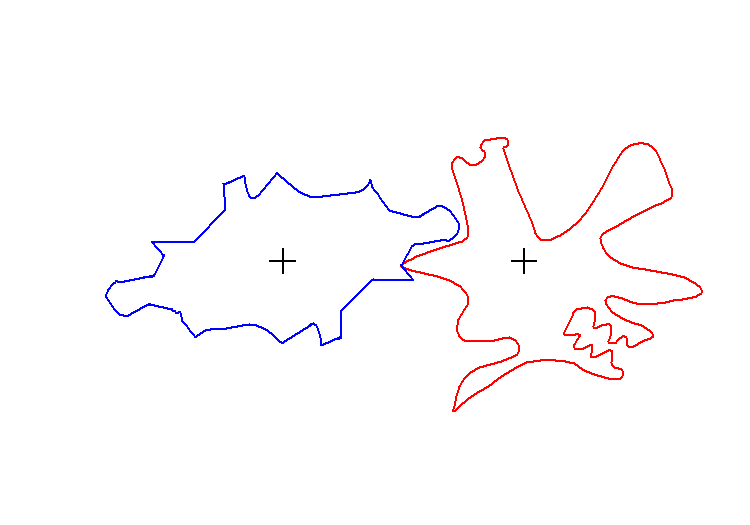
Then we clean up the mess and we're left with two perfectly-meshing "gears". They're not a great shape for actually transmitting any torque, but they make a great proof-of-concept. And one nice thing about doing this with software instead of cutting shapes by hand is that we can churn out more gears as fast as we think them up, so a failed shape doesn't seem all that bad.
"Wow! But you said there would be code."
That I did! You can find it over here.
"But I want an analytical method to make this even more precise!"
Boy, I hear you. But it's some weird math. Especially if you want to change the gear ratio, like on a Nautilus Gear! That's a project for another day, though. For now, please direct your attention to this explanation of the approach I took.