The 12-bit dimmer: An electronics kit with an audience of two and a utility of nil
This is the story of a very special gift for a very special friend. It's an RGB LED controller with some unique properties. The end result is full of little nods to our shared love of playfully unhelpful user interfaces. I call it "good bad design," other people call it "subversive design" or "outsider UX."
The Design Process
I began designing the kit in secret. My initial ideas were:
- Make some kind of fun-to-assemble electronics kit, functionality TBD;
- No coding, no microcontrollers;
- Give it a front panel that looks like it belongs in a 1960's flight simulator;
- Maximize fun tactile elements like toggle switches, knobs, blinky lights;
- Use resistors with as many orange stripes as possible (she likes orange stripes).
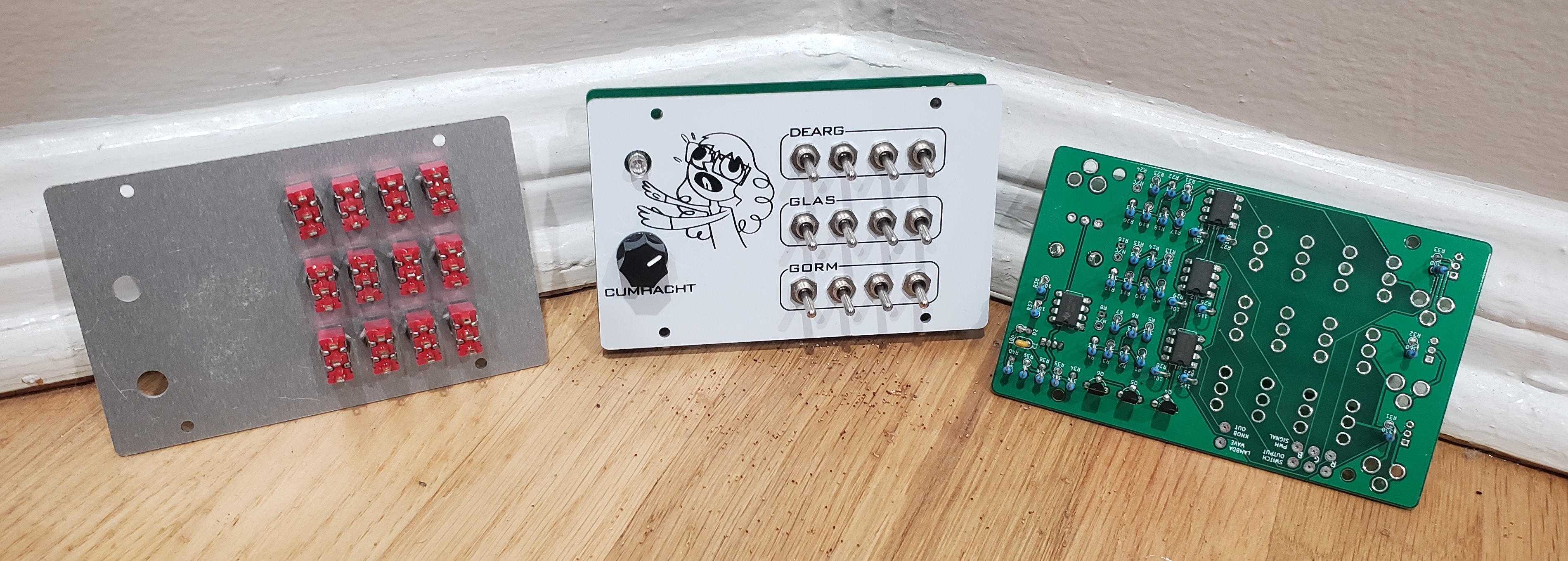
Ultimately, I settled on the RGB LED controller you see at the top of the page.
About the switches
The array of switches is probably the most noticeable feature. Well, actually, the text in Irish might be the most noticeable feature. Or, rather, the exciteable cartoon girl is maybe the most noticeable feature. Point is, there are twelve switches and they are arguably quite noticeable.
The twelve switches control the brightness of the LED—four for red, four for blue, four for green. Think of them like four-bit fractions: if 0000 (all switches off) is a fully-off LED, then 1000 is at 50% brightness, 0100 is 25% brightness, 1100 is 75% brightness, 0101 is 31.25% brightness, and so on.
It would make a lot more sense to just use a knob instead of switches, don't you think? A knob would require less hardware and offer finer precision. It definitely makes sense to use knobs. That's why I used switches.
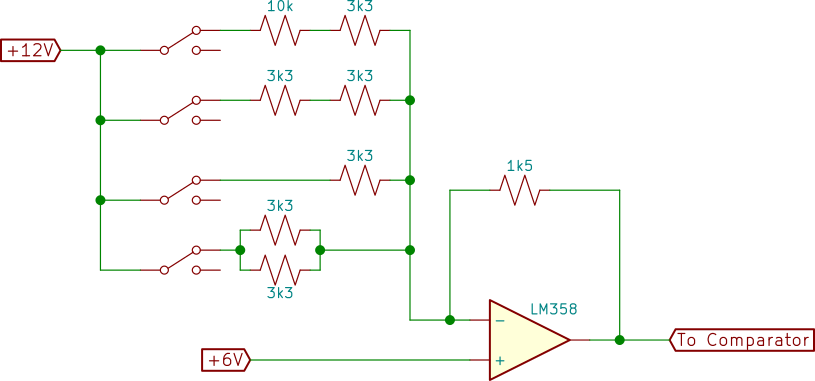
Each switch controls a path leading from the 12V rail to an op-amp acting as an inverting adder. The positive op-amp input terminal is tied to 6V, providing the upper limit on output. The four switches let the user set the output to one of 16 voltages, roughly evenly spaced between 0V and 6V.1 This gets converted to a PWM signal, described below.
A closer look at the DC-to-PWM circuit
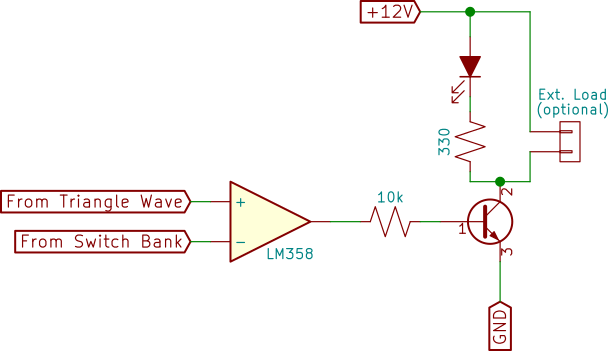
We can't halve the brightness of an LED by halving the voltage. Instead, we need to translate the DC voltage between 0 and 6 volts into a pulse train with a duty cycle between 0% and 100%. There are lots of ways to generate a pulse train with variable duty cycles, but I didn't find any that satisfied my requirements:
- Achieve any duty cycle between 0% and 100%;
- Maintain a linear correlation between input DC voltage and output duty cycle
A small aside: the famous Atari Punk Console fails both these requirements, and I'll be addressing that in another project.
The solution I settled on is convoluted and I love it. First, we have an oscillator which outputs a sawtooth wave between 0 and 6 volts. The frequency is about 1 kHz.2 The sawtooth wave and the switch bank output get thrown into a comparator, which outputs 12-ish volts when the triangle wave is above the DC voltage, and 0 volts when the triangle wave is below the DC voltage.
A closer look at the power knob
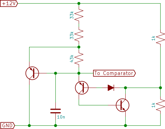
To power on/off the brightness controller, there's a knob. It doesn't need to be a knob; it's just turning on/off the comparator inside the circuit. It should be a switch. In fact, using a knob instead of a switch necessitates a lot of extra hardware. That said, I was honestly surprised by how much I love the sensation of literally turning the system on or off.
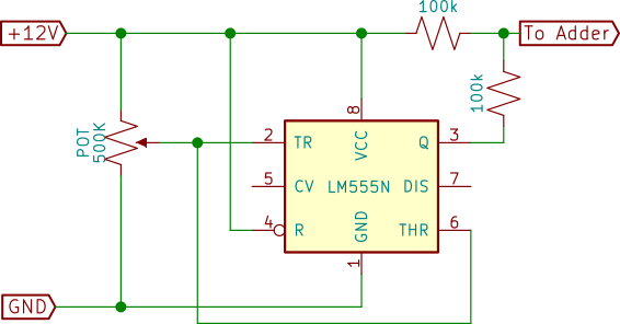
There's not much here, really. It's a bi-stable 555 timer3 controlled by the potentiometer knob. It's not actually directing power to the op amps or the oscillator circuit; rather, it drives the positive input to the inverting adder op-amps. When the knob is "off", it drives the adder output up to the 6V-12V range, which forces the comparator output to 0V regardless of the switches' positions. Turning the knob "on" lowers the adder output range down to 0V-6V, same range as the sawtooth wave.
Does it work?
Well, almost. We need to tweak the upper and lower limits of the adder to match the upper and lower limits of the sawtooth-wave component, which isn't as accurate as I'd hoped. If I were to make it again, I feel a lot more confident using a different sawtooth generator instead. But the circuit is pretty close to functional! And it worked in the sense that we assembled it together, learned a lot about soldering and electronics designs, and we used lots of resistors with orange stripes. So I'm real happy with it!
1. On the final PCB, there's space for an extra resistor, to alter the adder's upper/lower bounds, and the 1.5 kΩ resistor may need fine adjustment so that the switches span the whole six volts. I haven't actually done any fine-tuning yet. In retrospect, I should have made these both small potentiometers.↜
2. Actual frequency doesn't matter very much. As long as it's above 100 Hz or so, it will be fast enough to be unnoticeable.↜
3. I hope this causes a double-take. I very deliberately avoided the 555 timer in the PWM section of the circuit, where it would have been soooooo useful. And now I'm using a 555 timer in this complicated substitute for a power switch? I find it real satisfying.↜